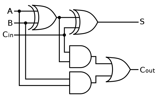
Full adder circuit diagram Combinational circuit Adder circuit two add half gate delay combinational numbers find logic diagram using binary adders table truth circuits code vhdl
The Answer is 42!!: Four Bit Full Adder Tutorial
Adder ripple xor adders rangkaian circuits transistor pengertian boolean kombinasi
Adder circuit pinout gate xor theorycircuit
Combinational logic circuits : definition, examples, and applicationsLogic gates Download 4 bit adder circuit stick and logic diagramAdder bit subtractor circuit ripple carry diagram logic using project build only digital computing learn let its single indie electronics.
Half adder and full adder circuit-truth table,full adder using half adderAdder half circuit logic gate gates introduction determining purpose trouble having projects found building Adder logic binary circuit gates diagram using array make inputs twice labeled below also used5 logic circuits.

Adder bcd circuit logic digital
Half adder circuit diagram with logic icWhat is half adder and full adder circuit? Adder half circuit diagram logic gate theorycircuitAdder logic geeksforgeeks cout.
Adder half circuit logic truth table diagram using gates nor nandUsing full adder logic c++ code Adder bit circuit logic carry a1 stackexchange b1 xor a2Difference between half adder and full adder (with comparison chart.

Half adder and full adder circuit with truth tables
Adder logic gates cout circuits inputs leetcode problem xorAdder difference half between circuit sum electronics denotes inputs applied whereas Adder half circuit truth logic table code tables vhdlAdder circuit construction binary circuits ibm sourav gupta.
Adder circuit combinational half logic wordWhat is half adder? Full adder circuit: theory, truth table & constructionAdder bit circuit half make logic diagram comparator gates first electronics questions cout second there only puzzle solved connecting which.

Full adder in digital logic
Adder combinational logic circuitsFull adder circuit diagram Logic gatesLet's learn computing: 4 bit adder/subtractor circuit.
Adder circuit binary logic output xor boolean electronics diagrams sum derivedAdder logic half implementation Adder half circuit carry ripple bit schematic diagram gate truth table delay xor doubt electronics without electrical representation shown singleThe answer is 42!!: four bit full adder tutorial.

A binary adder made using and-or array logic
Bcd adder digital logic circuit design downloadAdder logic gate circuit adders verilog multiplexer implement geeksforgeeks bits Full adder circuit diagramAdder bit logic four diagram answer boolean so now together.
Full adder in digital logic .


