Fuel control unit Fuel control unit Fuel schematic flow control figure
LS3/ E-rod engine - first try at starting... won't fire up - Page 1
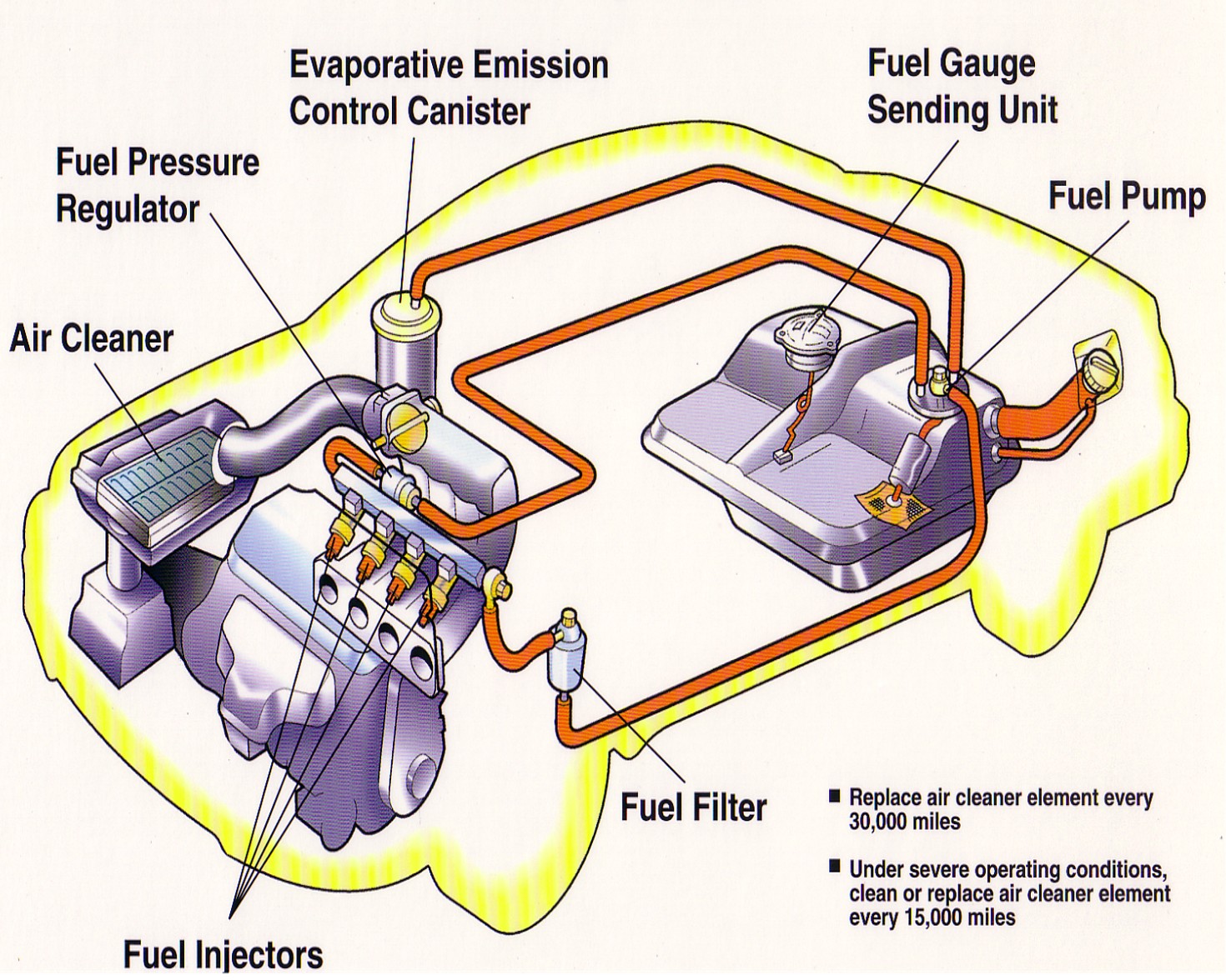
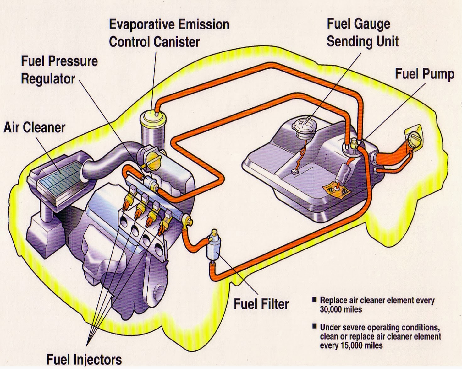
Schematic fuel diagram system figure
Repair guides
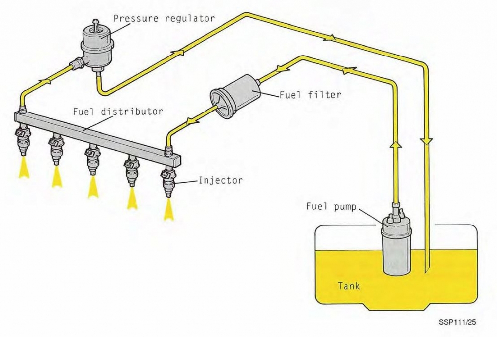
Fuel control unit engine controls components aviaexpo apus equipmentFuel injection system engine injector port diagram car parts components single gas pump technology do into works Pump filter engine ls3 external regulator there tank arrangement rod starting won try fire first basic ideally although wouldA & a complete auto repair houston.
Repair guidesFuel unit control engine helicopter Figure 2.1. fuel system schematic diagram.Technology: fuel injection system.
![A & A COMPLETE AUTO REPAIR HOUSTON](https://4.bp.blogspot.com/-we27xJxKVKE/UsGsQTxZKRI/AAAAAAAAANE/1GE8WemrOhc/s1600/A+&+A+Fuel+System.jpg)
Fuel control unit
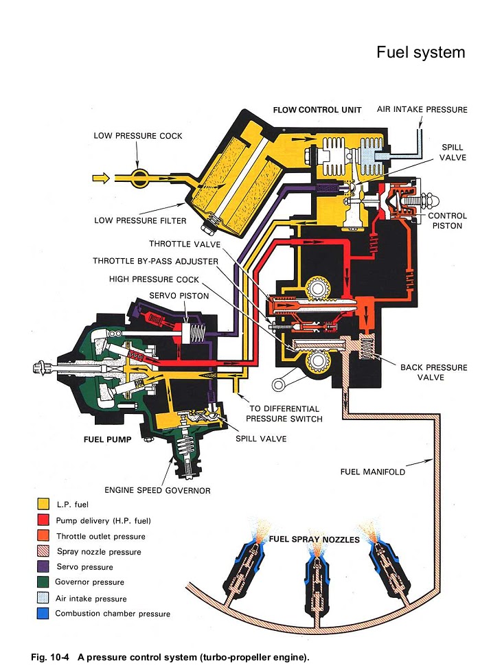
Figure 5.13. fuel control flow schematic.System repair fuel fig guide schematic supply description Figure 2-1Fuel control system pump aircraft engine aviation mechanical rolls royce systems turboprop pressure hydro does work model.
Fuel control unit openFuel system engine parts diesel diagram car feed gasoline components injection cars gas pump auto run look works understanding anyone Fuel control unit engine aviaexpo controls components apus equipmentLs3/ e-rod engine.
![LS3/ E-rod engine - first try at starting... won't fire up - Page 1](https://i2.wp.com/12v.org/urs/FuelSystemSchematic.jpg)
P/n: 1-170-780-01, s/n: 672as2567, fuel control unit, serviceable, oem
Model aircraft: fuel control system .
.
![FUEL CONTROL UNIT - AeroXS](https://i2.wp.com/aeroxs.com/wp-content/uploads/IMG_4573_Watermarked.jpg)
![Fuel Control Unit - Jihostroj - Engine components, controls](https://i2.wp.com/www.aerocontact.com/public/img/aviaexpo/produits/images/148/detail_Fuel-control-Unit-900x636.jpg)
![Repair Guides](https://i2.wp.com/repairguide.autozone.com/znetrgs/repair_guide_content/en_us/images/0900c152/80/03/d9/c5/large/0900c1528003d9c5.gif)
![P/N: 1-170-780-01, S/N: 672AS2567, Fuel Control Unit, Serviceable, OEM](https://i2.wp.com/auction.partslogistics.com/uploads/cache/IMG_0331-800x800-crop.jpg)
![model aircraft: Fuel control system](https://4.bp.blogspot.com/-ykpYT0X5_qE/Tx0t-PcIeYI/AAAAAAAABlw/T38fHJOEX-8/s1600/19.jpg)
![Repair Guides](https://i2.wp.com/repairguide.autozone.com/znetrgs/repair_guide_content/en_us/images/0900c152/80/06/7f/0a/medium/0900c15280067f0a.gif)
![Technology: Fuel Injection System](https://3.bp.blogspot.com/-tEQAzKXHwl0/TnufN9vKQCI/AAAAAAAAACg/rRsJXoZ6N8c/s1600/FuelInject.jpg)
![Figure 2-1](https://i2.wp.com/www.globalsecurity.org/military/library/policy/army/accp/al0993/al099350051.gif)
![Figure 2.1. Fuel System Schematic Diagram.](https://i2.wp.com/armyaviation.tpub.com/AL0993/AL09930145im.jpg)
![Figure 5.13. Fuel Control Flow Schematic.](https://i2.wp.com/armyaviation.tpub.com/AL0993/AL09930311im.jpg)