Gpio happens controllers gpios direction actually when set block stack Control raspberry pi gpio with adafruit io to trigger an led Running a mosfet from 3.3v gpio output
GPIO | SJSU CMPE Embedded Courses
Rpi.gpio update and detecting both rising and falling edges – raspi.tv
Gpio type1 polarity dip3 vin reversed normal circuit switchers
Gpio adafruit io circuit diagram raspberry pi trigger led controlHow to design the gpio circuitry Gpio layout output: a gpio pin designated asGpio raspberrypi kontrolle.
Gpio controller block diagram input purpose output generalGpio 14core Gpio leds resistors udoo scegliere arduino domotica raspberrypi eccoPi adafruit buttons raspberry sounds playing using gpio cobbler important note things.

Gpio stm32 ports pins lecture connected led figure
Gpio functions internal high configuration input output pullGpio output resistance – 2n3904blog Gpio circuit circuitlab example descriptionGpio pinout – "impartit".
Circuit diagramGpio presentation From its reference guide-the full gpio map [8].Gpio circuitry interfacing hardware.

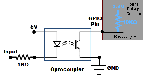
Gpio raspberry pi input circuit optocoupler opto rpi slotted schematic connect use current resistor doorbell hobbyist io gif detector open
How to design the gpio circuitryGpio pinout Purpose general gpio circuit hackaday diagramStm32 gpio lecture 1 : gpio pin and ports.
The raspberry pi hobbyist: gpio input circuitGeneral purpose i/o: how to get more Understanding how pic gpio workExplainingcomputers.com: using raspberry pi gpio inputs.

Gpio pinout impartit interface nerdytechy
Gpio block diagram [3]Gpio controller Gpio on tumblrGpio raspberry pi input circuit voltage current output electrical microcontroller schematic diagram levels mcu rpi pull read 3v down mosfet.
Gpio output resistance circuit schematic low high impedanceGpio input circuitry output Gpio useGpio example.

Gpio information for switchers
Gpio designatedGpio pin wiring for leds and their resistors Pi gpio homepage return videosGpio its.
Gpio circuit rpi both falling raspi edges rising detecting update testing tv makeGpio work pic does understanding mean clock symbol yellow .
![GPIO Block Diagram [3] | Download Scientific Diagram](https://i2.wp.com/www.researchgate.net/profile/Gurmohan_Singh/publication/311225981/figure/download/fig7/AS:649610641027073@1531890654276/GPIO-Block-Diagram-3.png)