10+ half adder diagram Cmos adder Adder cmos vlsi circuits circuit implement stack
projectiot123 Technology Information Website worldwide - electronics
Cmos adder technique cdu circuits implementation vlsi
Schematic diagram of existing half adder using static cmos technique
Cmos adder schematic logicHalf adder cmos layout using nand gates in microwind Cmos adder nandSchematic diagram of existing half adder using static cmos technique.
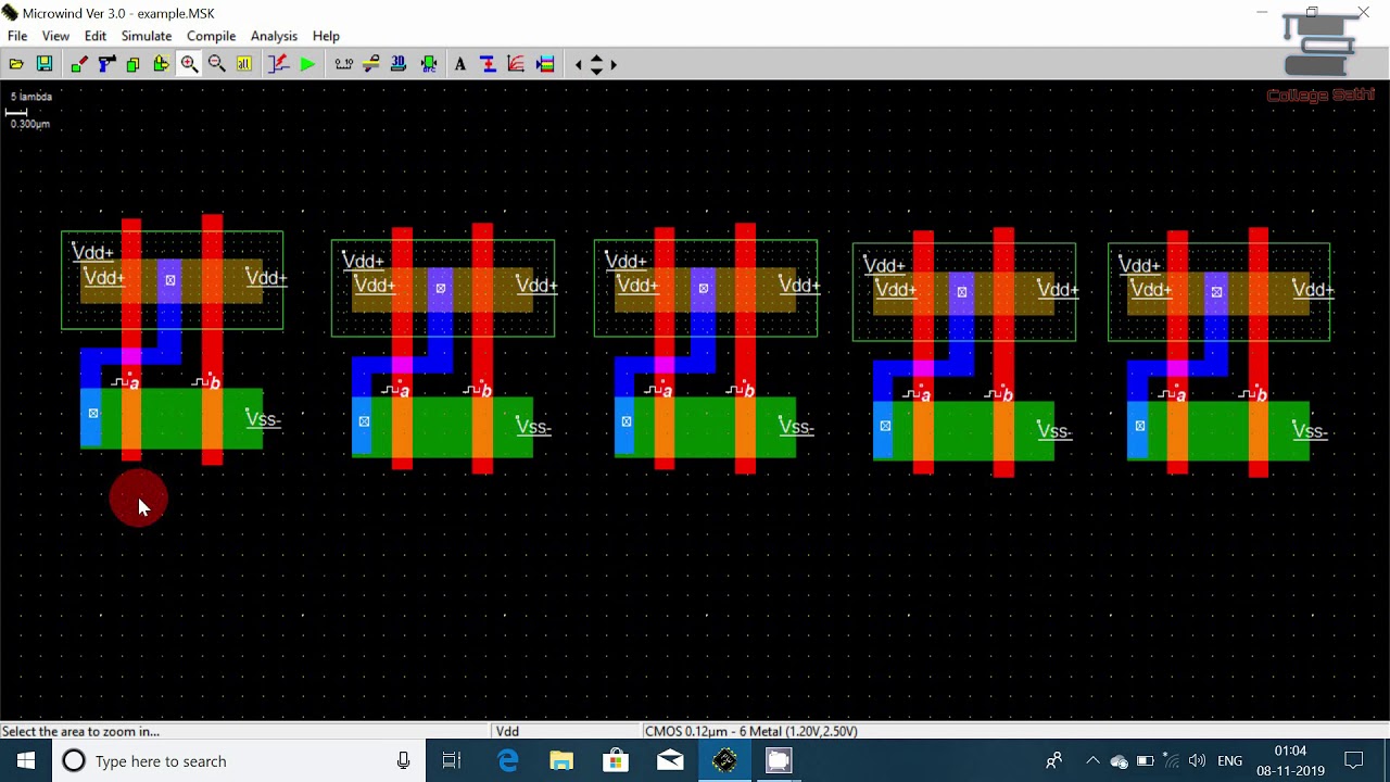
Cmos half adder using microwind10+ half adder diagram Adder microwind cmos half usingAdder half logic gates introduction.
![Schematic diagram of existing half adder using Static CMOS technique](https://i2.wp.com/www.researchgate.net/profile/Sivakumar-Murugesan-2/publication/320557527/figure/fig3/AS:552478475288576@1508732541606/Schematic-diagram-of-existing-half-adder-using-Static-CMOS-technique.png)
Adder cmos logic
Adder cmos transistor logic immunity assessment missions mitigation predictiveCmos adder Schematic of full adder using cmos logicProjectiot123 technology information website worldwide.
Cmos full adder design [10]Adder raspberrypi building Schematic diagram of existing half adder using static cmos techniqueAdder half logic gate using gates nand only combinational sum implementation circuits electronics tutorial carry output expressions shows combinations including.
![Half-Adder | Combinational logic circuits | Electronics Tutorial](https://i2.wp.com/www.electronics-tutorial.net/wp-content/uploads/2015/09/HA.png)
Adder cmos conventional
Half adderAdder half cmos using circuit implement carry sum Conventional cmos full adder.Schematic diagram of existing half adder using static cmos technique.
Adder cmos using schematic existingSchematic diagram of existing half adder using static cmos technique Solved 6. create a cmos circuit to create a half-adder, or aAdder gates half logic xor cmos mirror schematic diagram implemented instead why implementation optimized equivalent functionally construction just pipe stack.
Cmos adder circuits circuit arithmetic logic
Cmos adderCmos arithmetic circuits Schematic diagram of existing half adder using static cmos techniqueCmos adder schematic.
Why is a half adder implemented with xor gates instead of or gatesLayout adder bit lab following Cmos adder bitAdder half cmos layout microwind vlsi using software.
![HALF ADDER | USING CMOS | MICROWIND SOFTWARE | LAYOUT | DESIGN | VLSI](https://i.ytimg.com/vi/SsZLpdMBvLw/maxresdefault.jpg)
Adder cmos conventional inputs circuit circuits majority generator cell
Cmos half adder using microwind software .
.
![Schematic diagram of existing half adder using Static CMOS technique](https://i2.wp.com/www.researchgate.net/profile/Sivakumar-Murugesan-2/publication/320557527/figure/fig2/AS:552478476967937@1508732541540/Schematic-diagram-of-conventional-multiplexer-using-Static-CMOS-technique_Q320.jpg)
![Schematic diagram of existing half adder using Static CMOS technique](https://i2.wp.com/www.researchgate.net/profile/Addanki-Purna-Ramesh/publication/343451757/figure/tbl2/AS:921222992916481@1596648085940/Delay-for-Logic-Gates-Basic-Modules-Low-Power-Adders-using-CMOS-and-GDI-Logic_Q640.jpg)
![10+ Half Adder Diagram | Robhosking Diagram](https://i2.wp.com/image.slidesharecdn.com/cmoslab6latest-130422175713-phpapp02/95/half-adder-layout-design-8-638.jpg?cb=1366653536)
![projectiot123 Technology Information Website worldwide - electronics](https://i2.wp.com/projectiot123.com/wp-content/uploads/2019/07/What-is-Half-Adder.png)
![10+ Half Adder Diagram | Robhosking Diagram](https://i2.wp.com/projects-static.raspberrypi.org/projects/halfadder/fbd927fdbca5dcb6631fad44fa49ec03feafd80c/en/images/fig1.png)
![Conventional CMOS full adder. | Download High-Resolution Scientific Diagram](https://i2.wp.com/www.researchgate.net/profile/Keivan-Navi/publication/249567605/figure/fig7/AS:668354977218569@1536359652538/Three-inputs-XOR-sum-function-circuit_Q640.jpg)
![Cmos Arithmetic Circuits](https://i2.wp.com/image.slidesharecdn.com/cmos-arithmetic-circuits-1207066311646791-5/95/cmos-arithmetic-circuits-7-728.jpg?cb=1207041112)
![Half Adder CMOS layout using NAND gates in Microwind - YouTube](https://i.ytimg.com/vi/zZ60QgPNljk/maxresdefault.jpg)